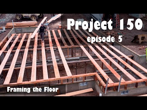
Tim Uhler revisits floor layout in this video, this time laying out for I-joists instead of dimensional lumber.
"...and so step one is going to be layout. In order to do step one, step one is going to be building some temporary bracing that we can set our planks on. This is going to make our life much easier, not just in terms of layout, but also in terms of scattering joists, nailing the rim, and then eventually installing our guard rails."
A solid work surface is the safest and most efficient way to get pretty much any job done, so they begin by setting up a scaffold system along the two walls they'll lay out. The scaffold planks are set so that the top plates of the wall will be about belly-height, making the process physically easier to accomplish.
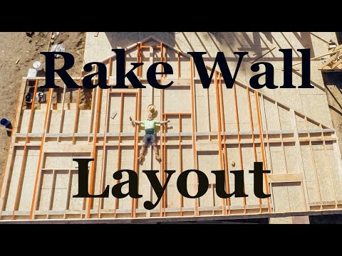
The perpendicular end walls are framed to the top of the I-joist, and Tim promises to follow up on that in a future video.
Laying out an I-joist floor is different than a dimensional lumber one
The fact that this floor will be framed with engineered I-joists, instead of dimensional lumber, means at least two things:
- The first layout mark requires slightly different math
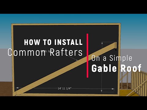
- The joists can span the whole darned building
In this case, it also means a third thing:
- The flanges are different widths, so the "slightly different math" part is slightly "more" different
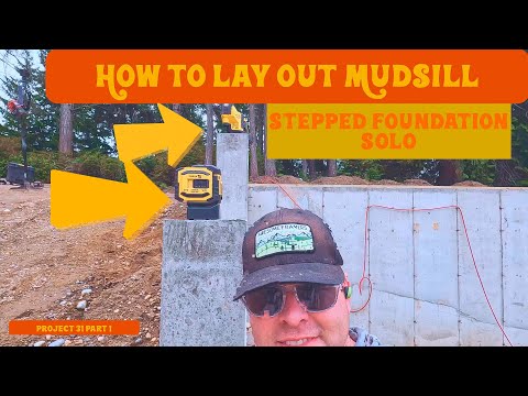
The flange on the first section of I-joists is 2-3/8 inches wide, so half of that is 1-3/16. Subtract that from 16 to find the first layout mark: 14-13/16. From here, Tim draws the layout line, autographs the line, and tacks a nail into it to hold the dumb end of his tape. Don't forget to pull or drive that nail after you finish laying out the wall. It will quickly become a tripping hazard.
Tim works one wall while Kyle works the other at the far end of the house. They double-check the numbers and math as they go. As it turns out, verifying the numbers paid off because one end doubled the offset by mistake, which would have made the beam and all of the floor joists crooked. Because subfloor sheathing does not come in trapezoidal shapes, this would have been a disaster.
Editor's note: I actually know a guy who made this mistake but didn't catch it until he was sheathing. He pulled the I-joists to the panel edges as much as he could and cut trapezoids to fill in the rest. I guess he thought no one would ever look at the framing from below, in the basement. smh.
Layout defines the joist centers, not the edges
After establishing one section of the floor, which has 2-3/8 inch wide flanges and ends with a 3-1/2 inch LVL beam, Tim moves to the next section of the floor, with 1-3/4 inch flanges. He cannot pull the layout for this new section simply by moving 16 inches from the previous layout lines because the flange widths are different. Instead, he needs to keep the centers 16 inches apart and let the edges vary.
To get the first joist placement, he pulls a steel tape all the way back from the corner to keep the numbers honest. He marks the center of the I-joist and then marks the edges, 7/8-inch on either side. Now he can plop a nail in the plate and pull the rest of the layout.
Because the joists are long enough to span the whole house, there is no need for alternating to different sides of the layout line, so there are fewer opportunities for simple mistakes. Upcoming videos will cover spreading and rolling the joists, and nailing the whole floor frame into place.
")


